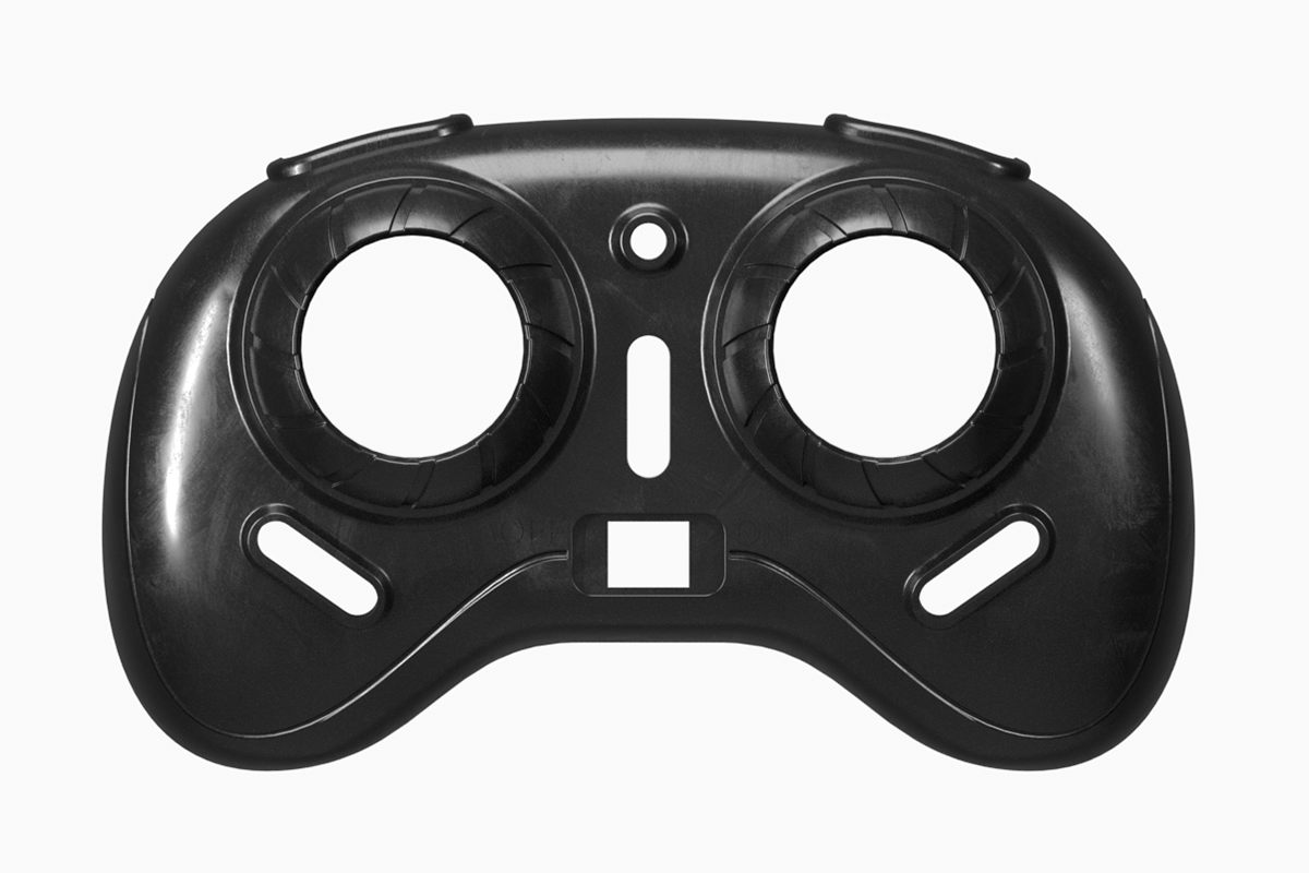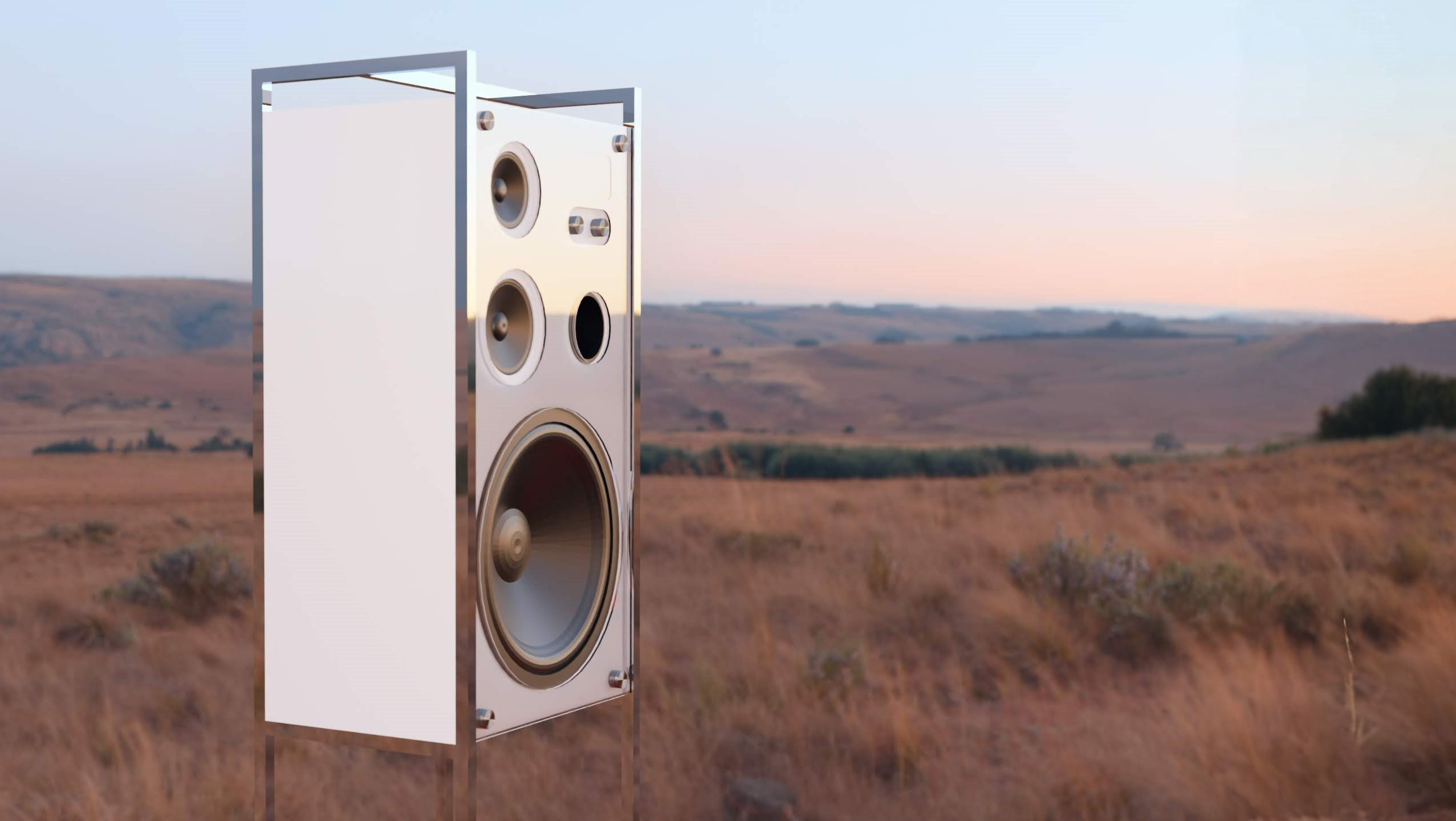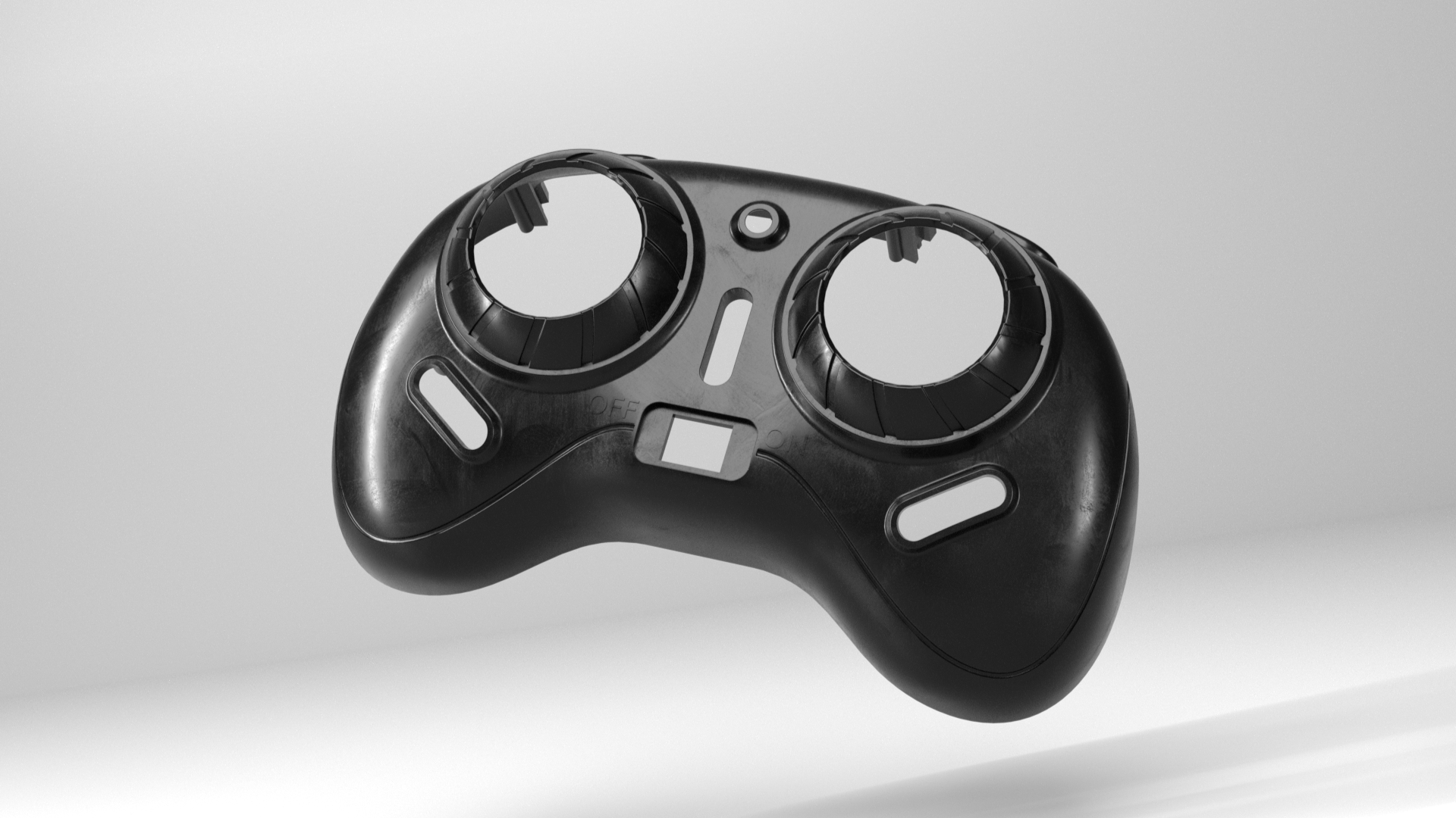
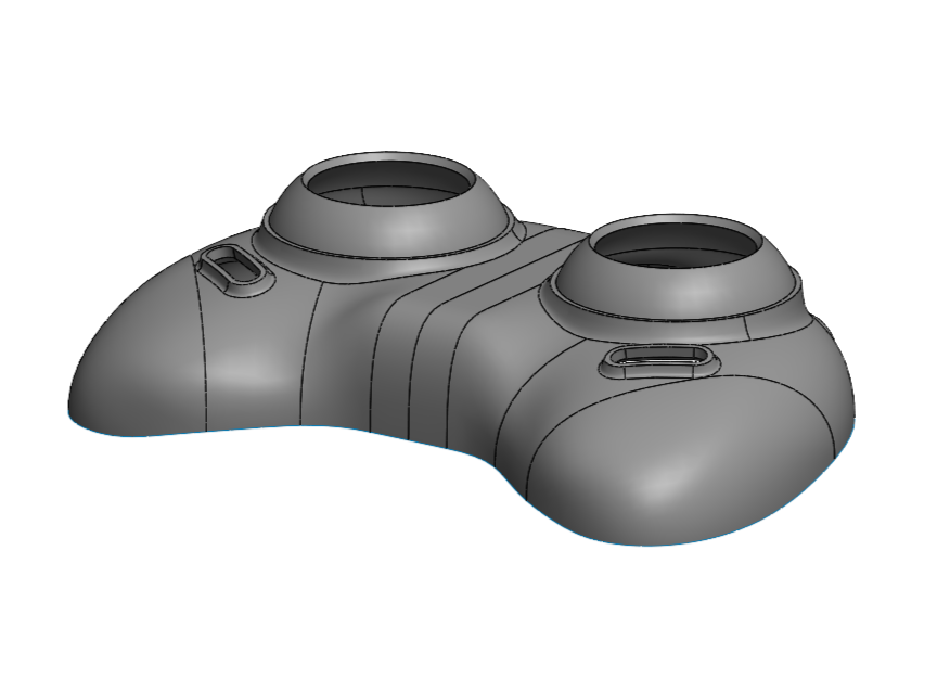
Above is a rendering of the quadcopter controller cover, as seen below. It was modelled in Solidworks and rendered in Blender.
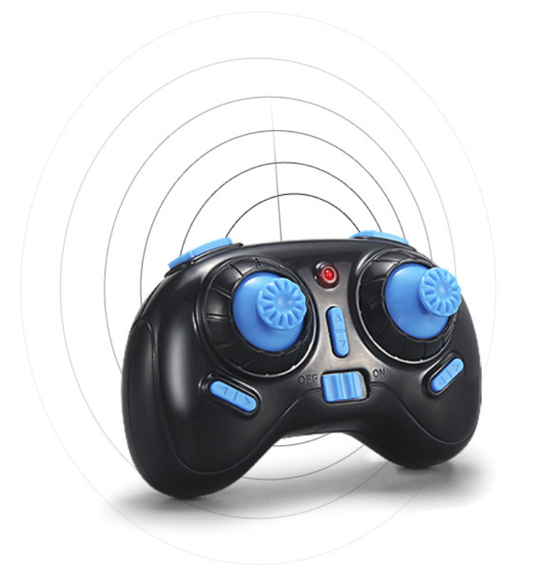
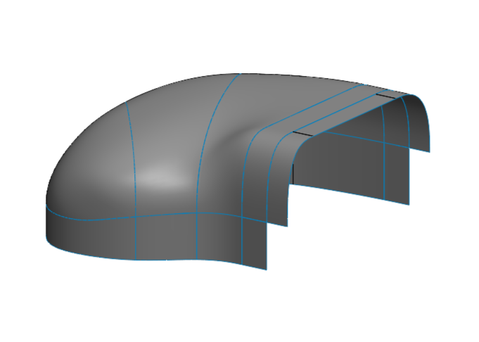
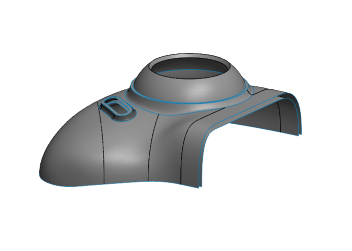
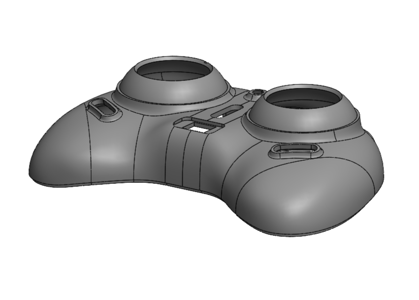
The process I used to construct this part in SolidWorks goes as follows. The product is mostly symmetrical so I only modelled half of it to start. I did this using orthographic photos of the product. I outlined the product in SolidWorks and created the parting line and section line at the halfway point. This was done with surface extrusions and projected lines. These extrusions could be used to reference and create the actual surface of the object as the surface needed to aim down and be symmetrical. By doing section boundary fills and surface fills I was able to make the overall shape of the surface. From there I was able to use offsets and projected sketches to make the places for the buttons.
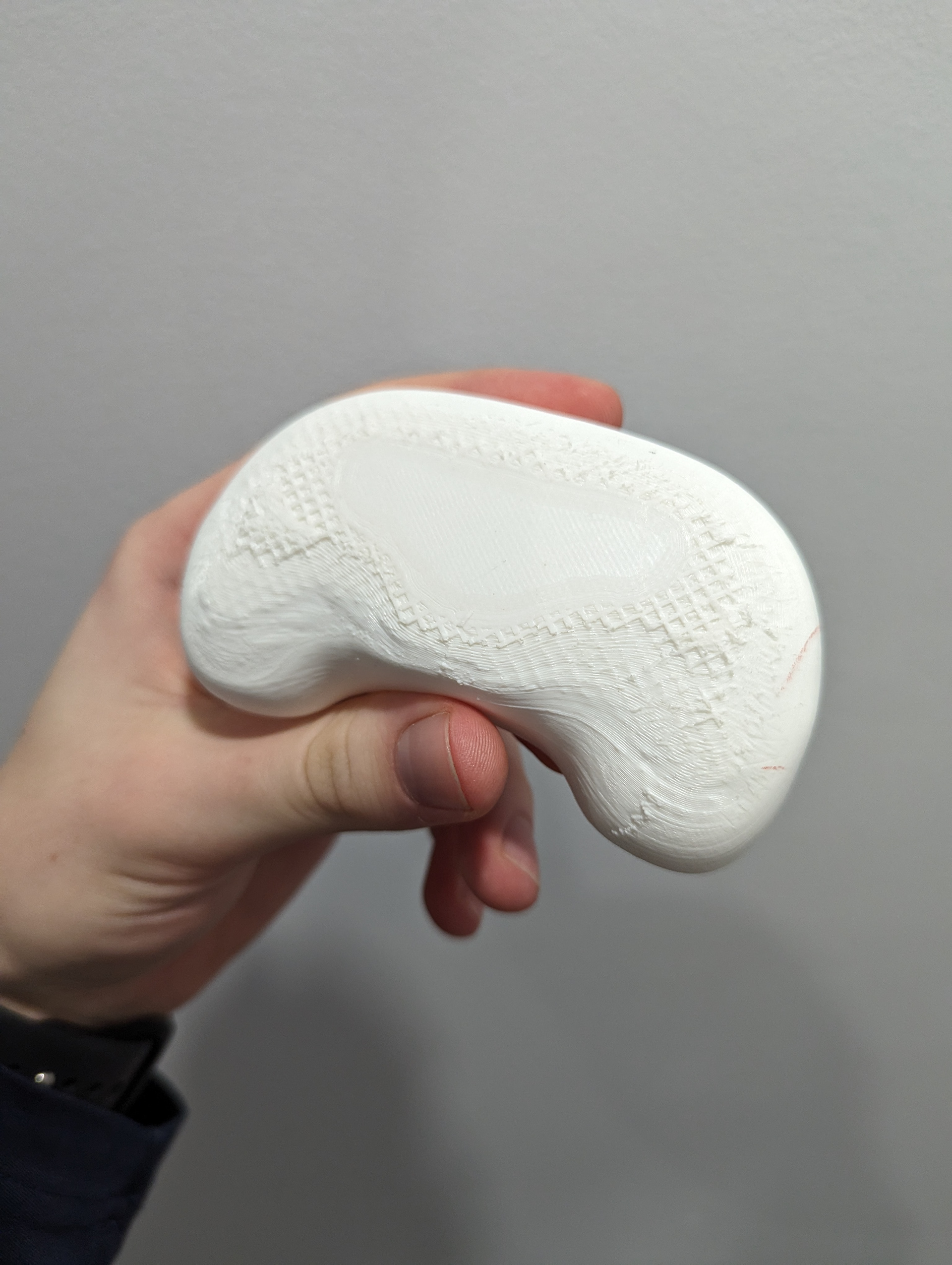
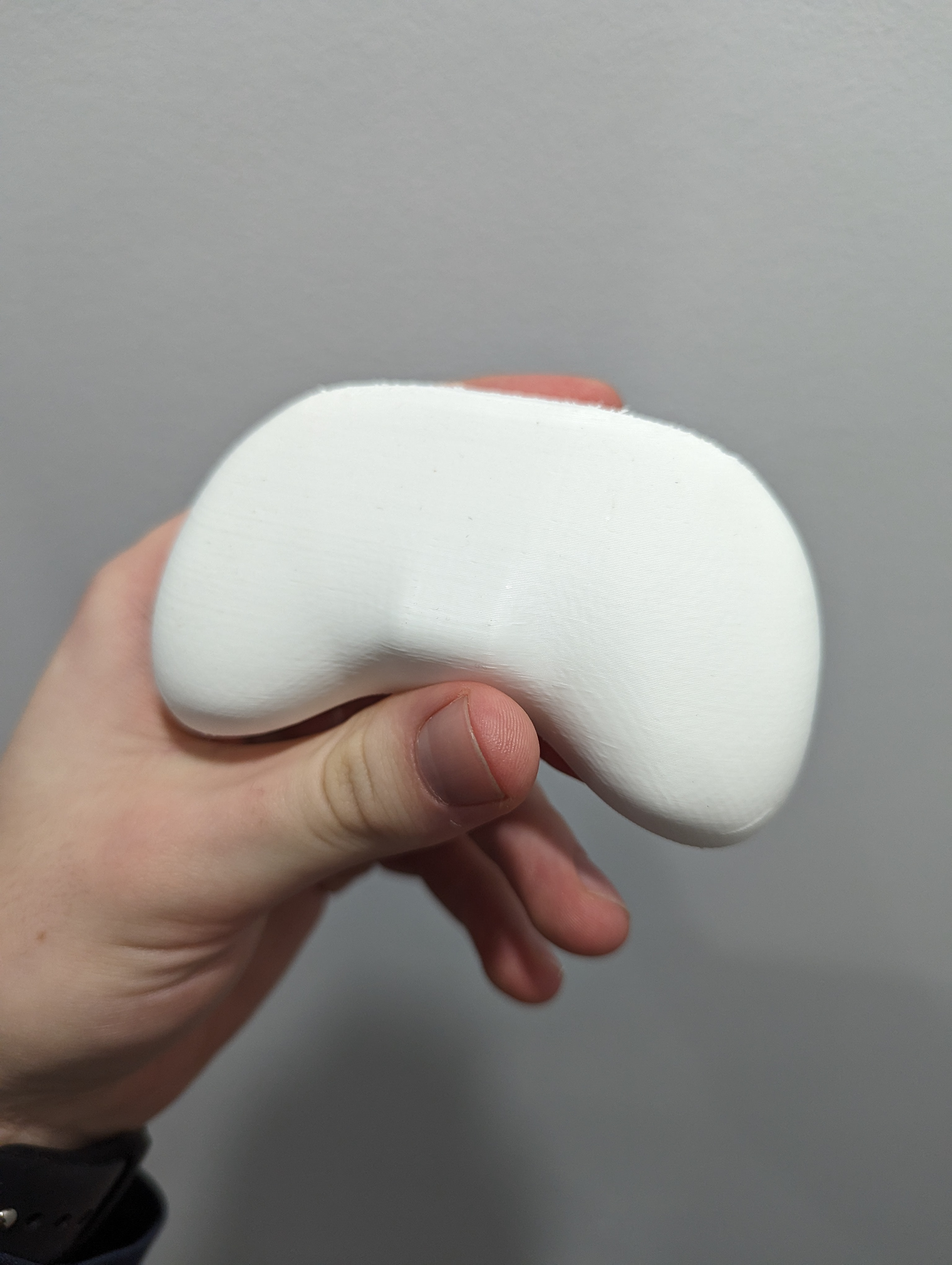
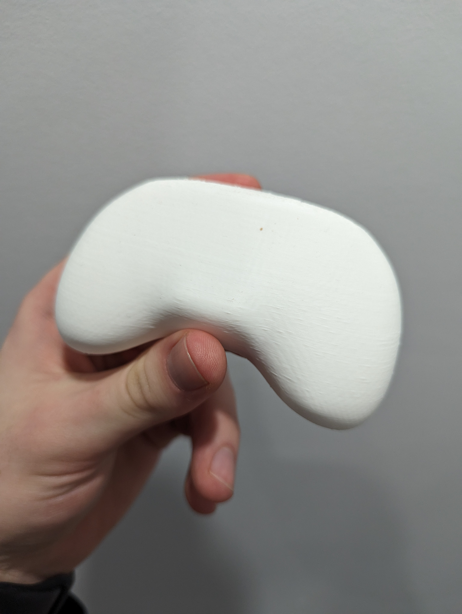
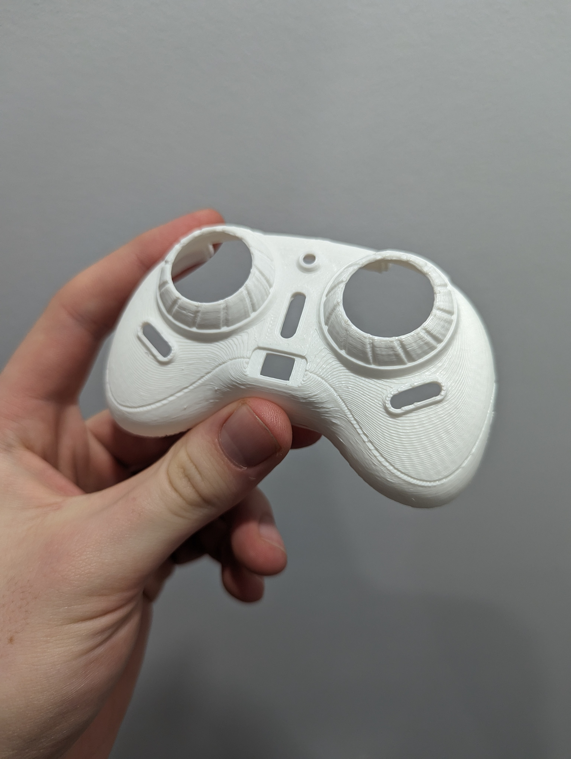
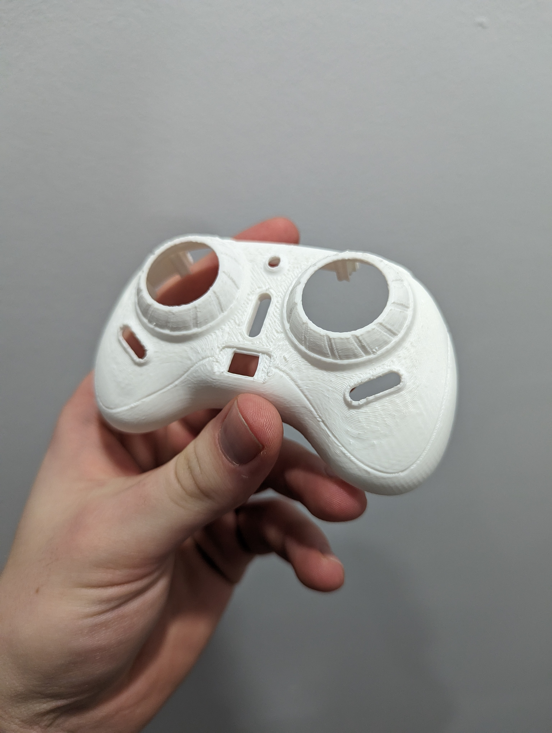
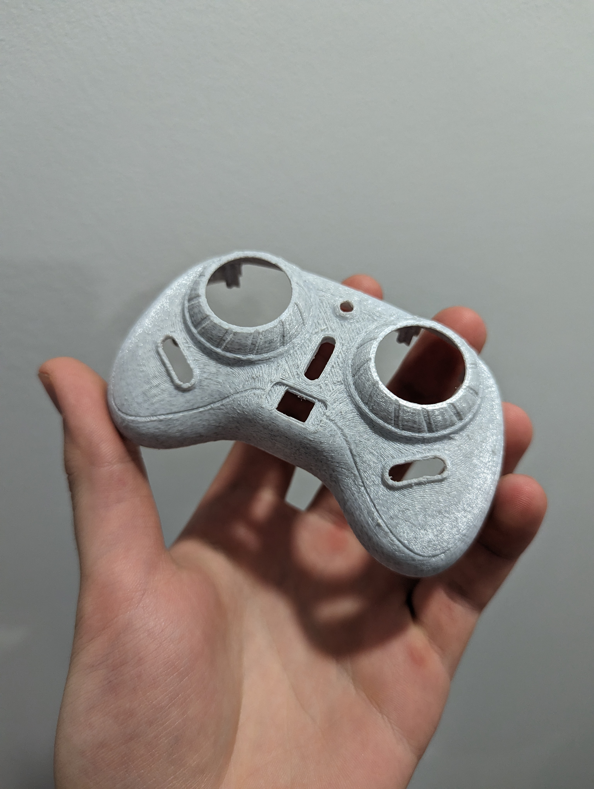
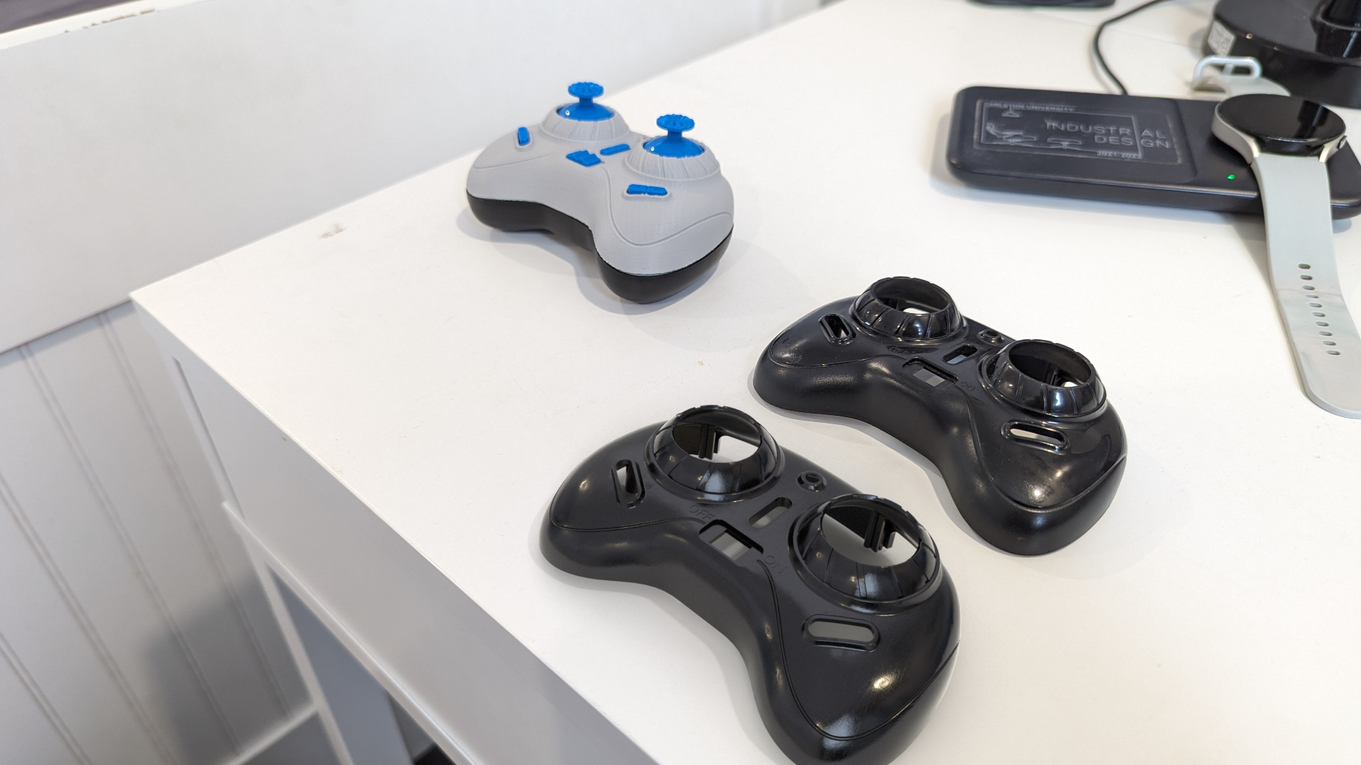
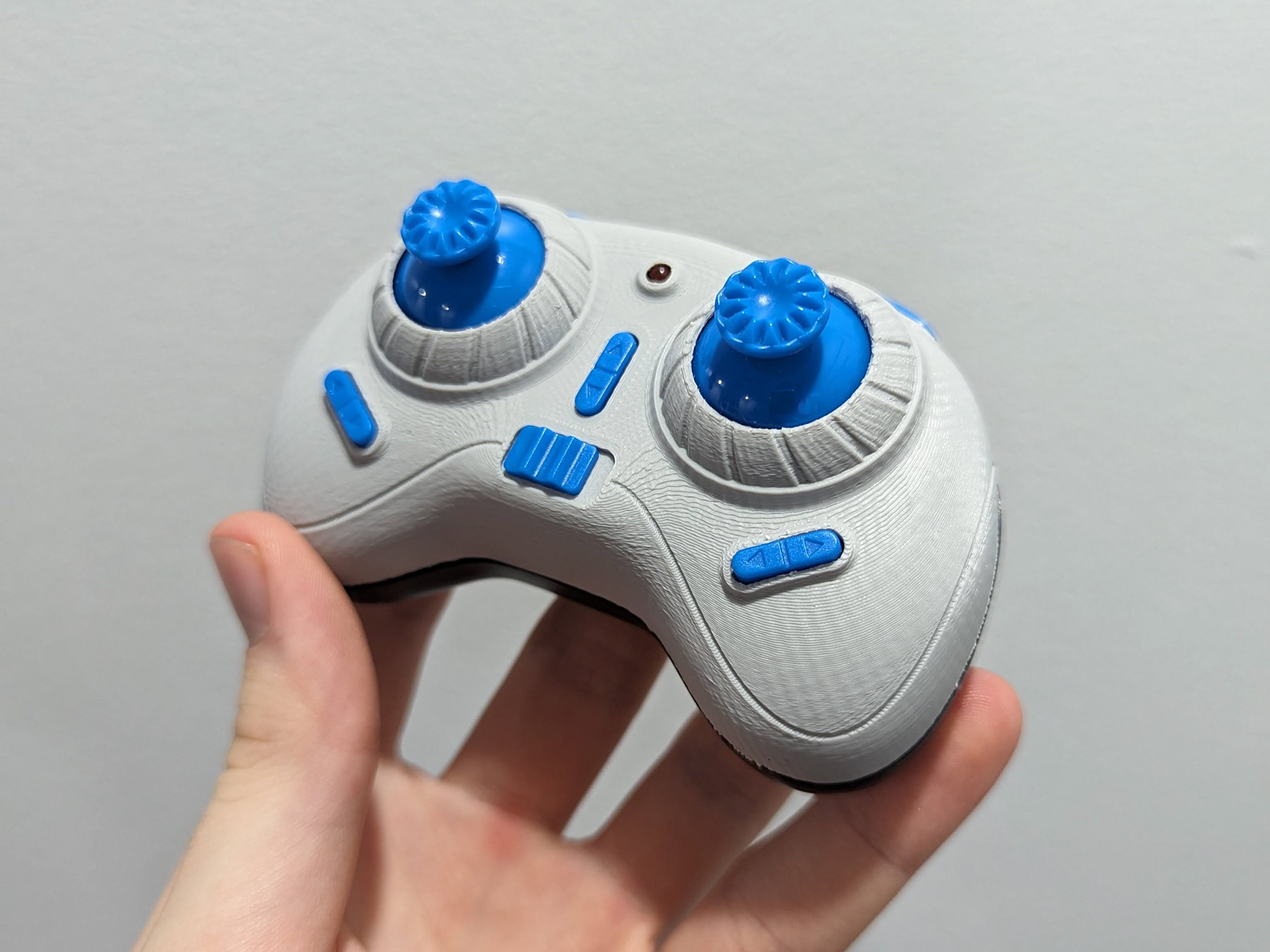
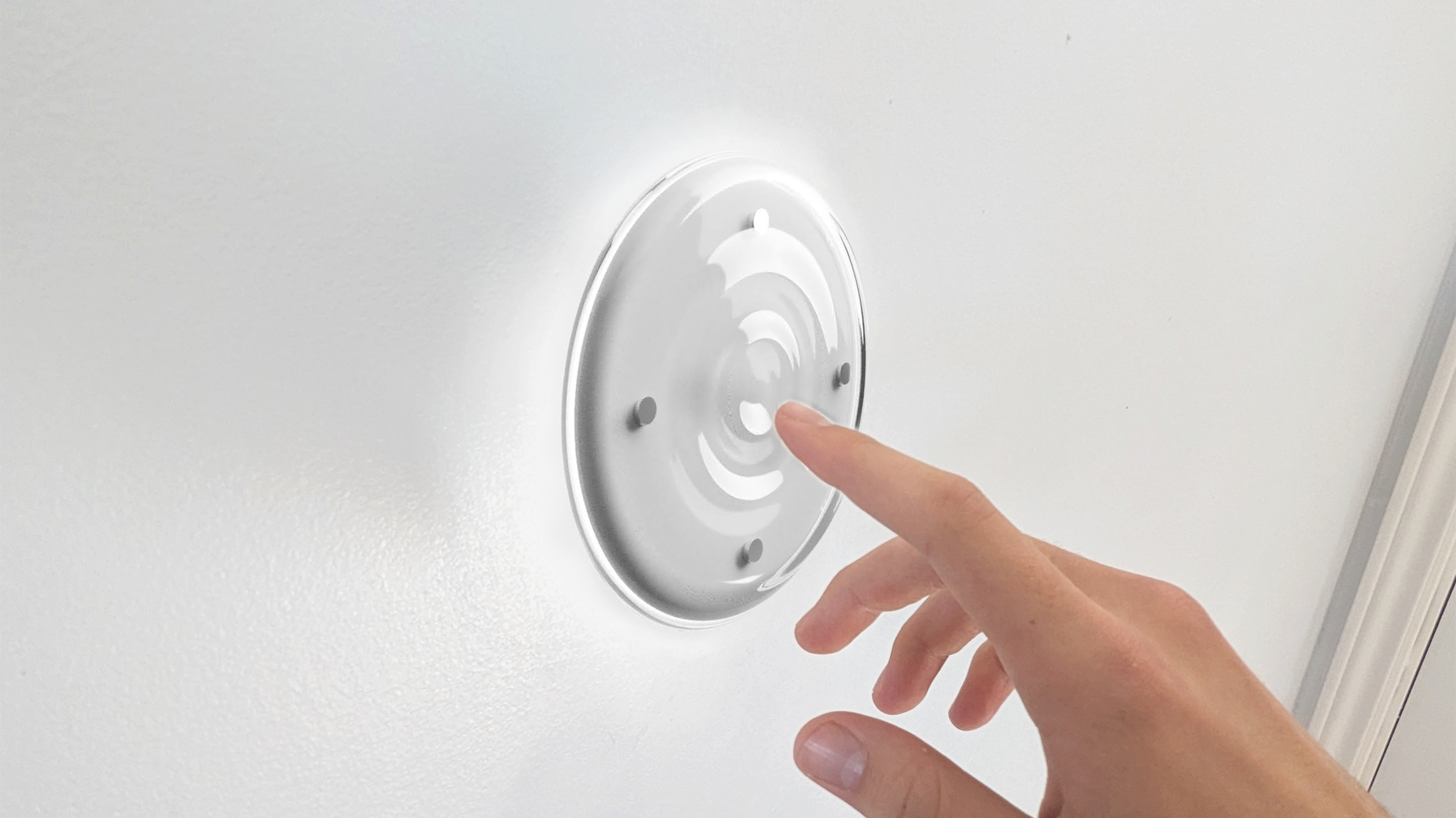
The images above are a series of test prints I did up until I got it to fit properly. Below is a comped render done in Blender. The model on the left is the final 3D-printed part in place with all the pieces. The Part to the right is the original part and the rendered model is the one at the bottom.